I spent a whole day researching and finding the tools, parts, and kits necessary for creating a Two Seater Go Kart for you guys. If you have a few spare hours and have always wanted to build your own go-kart, then this is the post for you. The process of building a go-kart seems daunting at first glance.
But it’s easy to break down into manageable chunks, and I will guide you on how to take things one step at a time in this guide. In this guide, I will outline the basics of how to build a Two seat Go Kart from start to finish. Remember that Go Karts aren’t meant to be ridden on public roads. These aren’t full-sized automobiles, so you need to pay attention to the city rules and regulations before you take your DIY Go Kart out on the road.
Now that the introduction part of the project is done, let’s look at how to create a DIY Two Seater Go Kart at home from scratch.
DIY Two Seater Go Kart – Parts, Tools, and Material Needed
For building a Two Seater Go Kart, you need to purchase these items and make sure to follow the specifications as described, as we don’t want you to make an alien object which can only serve as a showpiece and won’t even budge when you want it to.
Bulk Steel Materials Needed – Buy From Steel Yard

Tools Required – Buy From Local Hardware Store – Amazon Links Inserted

Go Kart Parts Kit – Buy Full Kit From Here

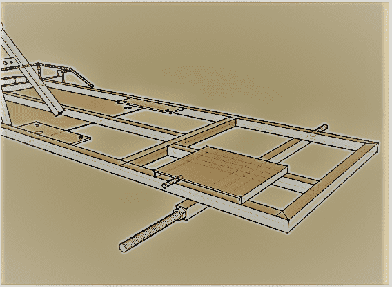
Now that the materials part is done let’s start the process of creating a Two Seater Go Kart going. But, first things first. You need to keep in mind where will the nuts, bolts, and other materials go while making a DIY cart. For your convenience, I have uploaded Two images that will help you in assembling the Go Kart. Let’s have a look.
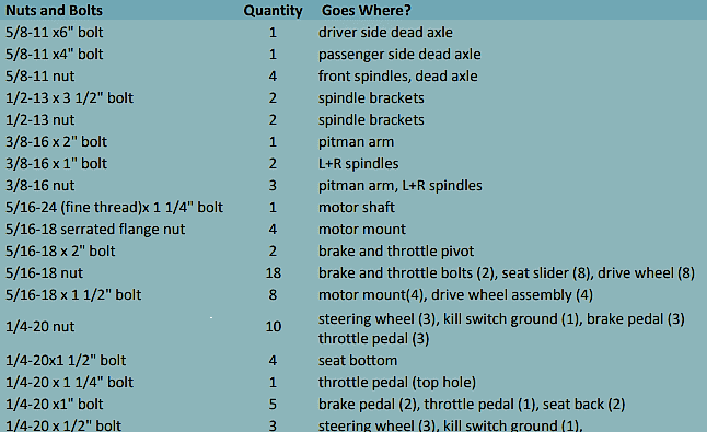

DIY Two Seater Go Kart – Blue Print – Building Frame
Now, let’s move on to building the Go Kart.
DIY Two Seater Go Kart – Plate Cuts
For your convenience, I have uploaded a diagram below that shows the 1′ x 1′ x 3/16″ piece of the steel sheet that you have to use to make all of the plate cuts. Keep in mind that this is merely an illustration and solely an example of my way of explaining things more easily. As you can see, a 1/8″ gap has been left out by me. You may use a razor blade and a straight edge to measure the measurements on a piece of steel and then carve them out. Use a center punch to create the holes and drill those out. The exact dimensions and orientation of each of the parts are included in the part where they will be required. So don’t worry about any of that yet.
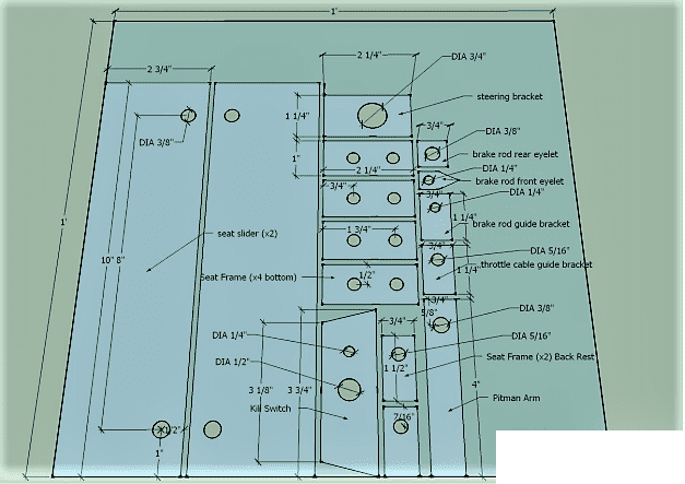
Points To Ponder
- There is a choice between 11-inch and 8-inch bolt-to-bolt designs for the seat sliders. The above graphic makes the assumption that 8-inch sliders will be employed.
- Cuts made with chop saws are measured at 0 degrees at 90 degrees real, and protractors are used to measure the actual angles of the cuts made with them. The dimensions for the chop saw degrees and the protractor degrees are also included in the blueprints.
DIY Two Seater Go Kart – Base Frame
Using a hacksaw, cut off your 1″x1″ steel tubing and solder it to the base frame. The corners of the bottom are cut at an angle of 45 degrees.

DIY Two-Seater Go Kart – Bumper
You need to cut out the components to build a bumper now that the basic frame section of the vehicle has been completed. Cut the rounded corners using a measurement from a chop saw at an angle of 22.5 degrees, which is equivalent to 67.5 degrees when measured with a protractor.
After that, drill holes centered at 5/16 inches in the tubing at 1 1/8 inches, precisely at the end of the tube. These holes will be used for the gas and brake pedals.

DIY Two-Seater Go Kart – Axle
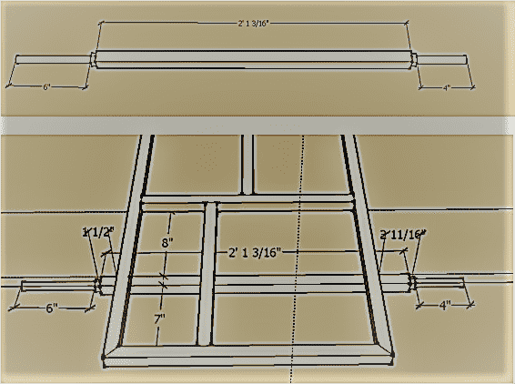
Now that the easy part is over, a section of square tubing measuring 1″ x 1″ should have a cutout measuring 25 3/16″ made in it, and it should have bolts measuring 5/8″ welded to either end of it. The nut and bolt with a measurement of six inches go on the side of the go-kart where the driver sits, and the nut and bolt with a measurement of four inches go on the side of the go-kart where the passenger sits. Weld the axle to the bottom of the base frame seven inches inward from the inside border of the rear of the kart frame. This will complete the axle assembly.
DIY Two Seater Go Kart – Floor Pan
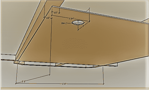
Once you have finalized the axle, keep it aside and start working on the floor pan. Weld the 16 gauge sheet metal that is located below the base frame. Next, drill Two holes in the region that was welded so that a bolt may be threaded through them. This bolt will eventually have a seat slider connected to it. The dimensions of the floor pan are 26 inches by 20 inches.

DIY Two Seater Go Kart – Motor Mount
The last step is to solder the motor mount to the frame in order to guarantee that the engine will not get in the way of the seat in any way. In order to get accurate readings from the measurements, you will need to align the engine when it is equipped with the sprocket and the clutch.
First, the engine shaft should be attached to the clutch, and then the drive wheel and axle stud should be attached. It is necessary to use a chain in order to properly align the teeth of the clutch with the teeth of the sprocket.
After ensuring that the slots in the motor mount enable the engine to go forward, secure the engine mount in place using tacks. The assembly of the Kart is finished after the engine mount has been soldered into place as the last step. To achieve a more precise alignment of the clutch and/or dead axle studs on the engine shaft, you may make use of washers or spacers measuring 5/8 inches and 3/4 inches.
DIY Two Seater Go Kart – Seat Frame
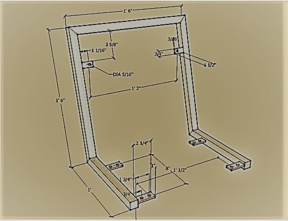
The seat that is provided for you in the Go Kart kit will not be attached to the actual Kart through bolts; rather, it will be attached to a frame that you will build separately. Following this step, bolts are used in order to secure the frame to the seat sliders. Cuts are made in the seat frame at either 37.5 degrees (as measured by a chop saw) or 52.5 degrees in order to create an inclination of 105 degrees from the base of the seat to the backrest (as measured by a protractor).
Point To Ponder
Use the picture that is shown above if the bolt pattern that is located on your seat sliders measures 8 inches. To accommodate sliders with an 11-inch bolt pattern, the underside of the seat frame should be extended by three inches, and Two more mounting brackets should be added so that they can hold the larger slider.
DIY Two Seater Go Kart – Seat Slider Brace
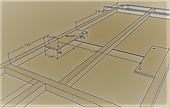
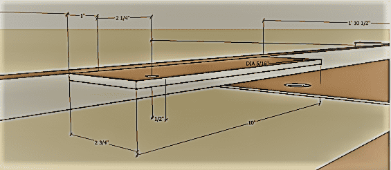
The seat slider can be attached to the frame by welding Two brackets to the sides of the Go Kart frame.
Point To Ponder
The bolt spacing on the seat slider plate should match that of the seat slider (for example, some seat sliders are 8 inches long while others are 11 inches long; an extending brace is required for 11-inch sliders). For instance, the brace that is used for sliders that are 8 inches long has dimensions of 10 inches by 2 3/4 inches, and there are 8 inches in between each of the holes. If the sliders were 11 inches, the bracing would be 12 inches by 2 3/4 inches, and there would be 11 inches between each hole.
DIY Two Seater Go Kart – Steering
To make steering, first cut a section of tubing measuring 3/4 inches in diameter and 11 gauges in thickness to a length of 18 inches, and then weld the two pieces together. You can see the pitman arm, a spacer, a tab that will fasten the shaft to the frame, and an angle iron that is 1 inch by 1 inch by one-eighth of an inch in the image that follows.

Following that, position the additional spacer that is 1 inch in length (you may need to grind the shaft near the steering hoop for a loose fit). After having a pattern of three holes drilled into the flat washer that corresponds to your specific steering wheel, the washer should be welded onto the end of the shaft.

After that, you need to put together the steering hoop as well as the brace for the kill switch. When cutting the hoop, an angle of either 39 degrees (with a chop saw) or 51 degrees is used (using a protractor).

After that, make sure that all of the dimensions are accurate. The hoop and shaft should be positioned such that they are perpendicular to one another.
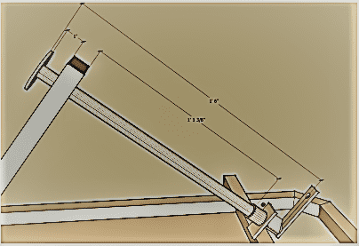
DIY Two Seater Go Kart – Spindle Brackets
Weld the spindle brackets after positioning them so that they are centered on the front axle. Even though it lacks camber and caster, this Kart has great steering despite not having those features built into it.

Point To Ponder
It is necessary to center the suspension brackets left to right if you have installed front spring suspension brackets (also known as springers). Nevertheless, the longer bracket must not be positioned up or down in any of the possible directions. It is recommended that there be a gap of one inch between the bottom of the bracket and the bottom of the front axle. This will allow for easier installation and removal of the bracket.
DIY Two Seater Go Kart – Brake and Throttle Pedal Stop Tabs
These tabs are used to keep the brake and throttle pedals in their respective resting positions and full forward positions when required. Make sure to perform due diligence while working on this part of the project.
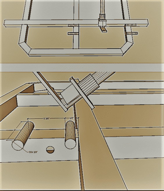
DIY Two-Seater Go Kart – Brake Band Stud
Attach the circular bar that is 3/8 inches in diameter to the frame by welding. This stud, which will serve as the band’s pivot point, will be the place around which the brake band will rotate.
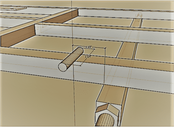
DIY Two-Seater Go Kart – Brake Rod Guide Tab
After the brake rod has been bent and inserted, you need next proceed to weld this tab onto the Kart. This should be done after the brake rod has been mounted. It is feasible to make small adjustments by bending the rod itself, even if the brake band has already been fitted.
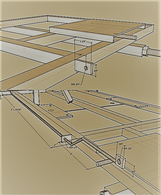
DIY Two-Seater Go Kart – Brake Rod
Make a bend in the circular rod that has a diameter of 1/4 inch, leaving excess material on both ends once you’re done. Before installing the brake pedal with the return spring, ensure that the rod is cut to the necessary length and that the eyelets are soldered to it.
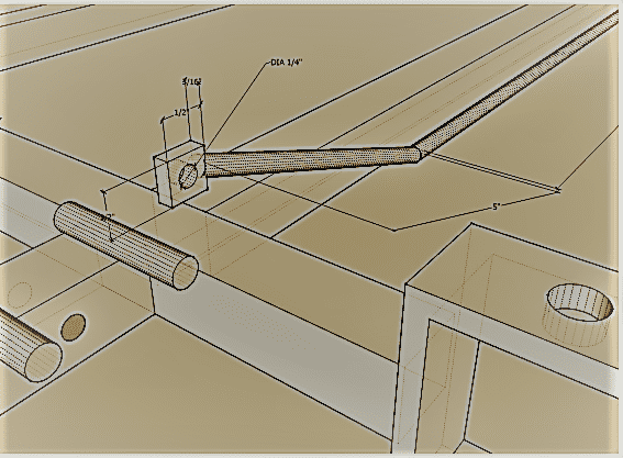
DIY Two Seater Go Kart – Throttle Table Guide Tab
For the throttle table, it is recommended that you weld this tab to the Kart at an angle of 45 degrees at about four inches back from the middle of the throttle pedal bolt hole.

DIY Two Seater Go Kart – Side Rails
Here are some side rails to give you a sense of what I mean. You are free to come up with your own design, or you may choose to duplicate it word for word. I created the go-kart I built so that it could seat both youngsters and adults, and I made sure to incorporate this feature. It is not necessary to have side rails, but having them gives you something to grip onto when you need to turn; hence it is highly suggested to have them. This particular one had its cuts are done at an angle of 35 degrees (as measured by a protractor) for the rear/high end and an angle of 55 degrees (as measured by a protractor) for the front/low end.

DIY Two Seater Go Kart – Foot Rest
Using a 3/8-inch diameter rod, bend it in a vice with a hammer to create a footrest for the passenger.
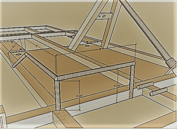
DIY Two Seater Go Kart – Final Product Blue Print
Here’s what our new Two Seater Go Kart will look like after every part has been made and assembled. Now that the hard part of soldering, welding, and sawing is over, let’s assemble this bad boy!

How to Build a Two Seated Go Kart: A Step By Step Guide
After you have created the frame and welded all of the parts together that were required to form a frame, now’s the time to build the double seated go kart. Here’s a step by step guide that will take you through the whole process.
Grab The Materials
Remember we asked you to collect the material. Now’s the time to use all of the go kit parts, tools (welder, angle grinder, drills, saws and measuring tools), steel including the tubing, plate and sheet metal and other hardware materials including nuts and bolts etc. Remember not to skip anything as we don’t want you to start looking for things while you will be building your dream two seated go kart.
Cut The Steel Plate
Let’s have a look at how to cut the steel plate precisely. Keep in mind to follow the instructions so that you don’t spoil the whole sheet while drilling holes.
Mark The Steel
First of all you need to mark the steel by taking out a straight edged marking tool. You can use a square or protracting tool to complete this. As we know that steel has kind of a rustic appearance, so it will be hard to see the markings on it when done with a pencil or a pen. Most of the experienced welders take the help of a soap stone to do so, because it performs well under light and when the welder’s cut n grind mode is used, we can see it clearly under the auto darkening welding hood. I went a different way and used a razor blade combined with a sheet rock knife to mark the sheet. Believe me it shows very well when I see it under my garage lights. For making sure that I am using precise cuts, as the cut off wheel is around 1/8” thick, I chose which side of the line to cut. I recommend that you guys should mark all the tabs and brackets at around 3/16” plate all at once.
Drilling Holes In Steel Sheet
Once you have marked the sheet, you have to decide where you will make holes in the 3/16” steel plate and tubing. Keep in mind that the brake and throttle pedals would require the holes to be drilled in the tubing on the bumper. So, let’s start drilling holes.
- Hold the center punch on top of the steel and start hammering it to create a divot. This will allow you to fix the sheet and it won’t move or walk while you will try to drill the holes in it.
- Next, take out a small diameter drill and create a pilot hole. Make sure to drill all the way down.
- Consider using the actual size drill bit to take out the drilled pilot hole.
Cutting The Plate And Tubing
There are numerous ways to cut the tubing and plate. Keep in mind that you will only need an angle grinder to cut this thick sheet and it does its job very well. Although there are other options like a plasma cutter, jigsaw and a chop saw. I used a 4 ½” angle grinder to do the required task. It cuts very fast, and besides the wheel attachments are quite cheap.
Remove The Burrs And Bevel The Edges
Once the sheet is cut, you will notice that the steel sheet will have small pieces of metal stuck to it. They were either not removed fully, or the edges might be uneven. You can easily remove those leftover burrs by running a wire wheel with an angle grinder over those.
If you have access to a smaller welder, you may enhance the steel’s fitting and weld penetration by beveling and deburring the edges of the piece. This will allow the weld to penetrate deeper into the steel. Beveling the edge of the tube is often done at an angle that is between 30 and 45 degrees to the cut that will be used to link two pieces of tubing together. This ensures that the beveled edge of the tube has a smooth transition between the two sections of tubing. To make a bevel, all you have to do is attach a grinding wheel to your angle grinder, and then cut away an angled part of the edge that will be welded. The end result will be a bevel.
So, now that the steel sheet is cut into fine pieces, let’s weld these parts together with the frame.
Welding The Base Frame
Creating a fine go kart frame is easier said than done. Although it is pretty straight forward but you have to pay attention to the whole process. Remember the blueprint in which we asked you to create different parts of the frame? Now’s the time to take those out and start welding those together. So, without further ado, let’s get going!
Square The Frame By Securing The Edges
To make sure that the base frame looks square and fine, put it on your workspace. Take out a square plane or plywood and put the frame on top of that. Next use the nails to secure the tubing, so that it doesn’t move while welding. Bracing the frame with nails is necessary because while you are welding the tubing together, you will notice that the tubing will start warping slightly.
Tack Welding The Frame
Just when you have secure the tubing, you should start welding the frame. Make sure that the tubing matches up correctly. After that make small tacks at the intersections of the tube. Ensure to stick the tubing intersections with four small tacks. Remove the nails when done. Welding the joints from every side will get you greater results so when you are welding one joint side and are done with that, flip the frame over to start welding the other side of the tube.
Welding The Bumper
Once you are done with the backend of the frame, repeat the same process for creating the bumper. Ensure that you have the holes drilled exactly in the center of the tubing from the end of the tubing. Check again if you have 5/16” pedal holes in center of 1 1/8” from the edge. Although it is not recommended to grind the welds on main part of the frame, but for smooth appearance and for aesthetic appeal you can grind the bumper welding.
Creating a Rear Axle
So, now that the base frame is welded together, let’s start working on creating a rear axle. Here’s how to do it.
Create a cut section of around 11 gauge 1”x1” square tubing of around 25 and 3/16 inches long. Another thing that you will need to build a rear axle will be two 5/8” diameter bolts. Keep in mind that the length for the bolts and axle stubs will be quite different as one bolt will be larger in diameter to allow the rear drive wheel assembly while the other bolt will be used to allow the passenger side of the wheel to work independently of the drive wheel.
It is essential to take notice that the rear axle that will be used in these designs is what is often referred to as a “dead” axle or a “one wheel drive” axle. This kind of axle is the simplest and least complicated form of axle that may be used in a vehicle. The bolt that secures the end of the axle that is attached to the driving wheel is a 6 inch by 5/8 inch bolt. On the other hand, the bolt that secures the end of the axle that is attached to the passenger side is a 4 inch by 5/8 inch bolt. Even though I used grade 8 bolts, you should really use grade 5 bolts if you want to be on the safe side.
Weld The Axle Stubs To The Tube
Keep in mind that welding the bolts or axle stubs to the fixed axle is of very much importance. As the axle will be the load bearing part of the vehicle, so you need to pay attention to the whole thing. Here are the steps of welding the axle stubs to the tubing of the two seated go kart.
- If you want to get the most out of your weld penetration, you should grind the edges of the tube ends so that they have a little bit of a bevel. I didn’t bother because the welder I was using was strong enough to weld through anything, but you should if you are dealing with a welder that is built for lighter duty. I didn’t bother because the welder I was using was powerful enough to weld through anything.
- Tack weld the bolts to the tube in four distinct corners that are across from one another from one another.
- Make use of a straight edge or a level in order to properly align the bolt so that all four of its edges are perpendicular to the tube. This may be accomplished by aligning the bolt. To ensure that the bolt is properly installed, use a hammer to tap it into position.
- Insert another tack in the space between the four that are already there to bring the total to eight.
- It is important to double check that the axle bolts have been positioned so that they run in a direction that is parallel to the tube.
- Weld the bolt to tube connection, beginning from one side at a time and working around the joint. After you have welded the first side of the axle, you need flip it over and weld the second side so that the axle does not distort excessively. This will help prevent the axle from breaking.
- If you just have a tiny welder, you may use the wire wheel attachment that comes with your angle grinder to polish the welds. You may give the weld more strength by doing several weld passes over the margins of the first weld. This will give the weld a greater overall strength. Only one pass was necessary for me to finish because of the power of my welder.
- Carry out the exact identical steps on the other end of the axle.
Welding The Real Fixed Axle
It is necessary for you to move the fixed axle in a direction that is counterclockwise from the head of the bolt that is linked to the go kart frame. This is essential due to the fact that the steering wheel and the passenger wheel link in two different locations. You will be able to maintain the same spacing between the frame and the rear wheels if you do this. A rundown of the procedures may be found as follows:
- Put the end of the axle that is attached to the 6-inch bolt on the side of the frame that is facing the passenger.
- Take the required measurements to figure out the correct space that should be maintained between the back of the go-kart and the axle that is secured. Double-check the distance that separates the front and the back axles, and make any required adjustments (they should be the same on both sides).
- Take a measurement of 1 1/2 inches from the bolt head on the driver’s side to the frame. On the passenger side, take a measurement of 2 11/16 inches from the bolt head to the frame.
- Put some welds on the frame of the axle in a few strategic places.
- Welding should be used to join the frame to the axle.
After you have finished building the homemade go kart axle and welded it to the frame, you can now take the parts for the axle assembly and do a dry fit to see whether or not everything worked out properly. This will allow you to decide whether or not everything worked out perfectly.
You are doing an amazing job. Just keep in mind that everything should be done in stages. Let’s have a look at how to install the floor pan.
Building The Go Kart Floor Pan
Once you have built the real axle and the bolts are welded onto those, the next step is to make the kart floor pan.
Material and Dimensions
The standard mild steel is used for the construction of go karts’ floor pans. This material has a thickness of 16 gauge, which is roughly comparable to an inch and a sixteenth. Go karts are driven on flat, circular tracks. This is the perfect combination of mobility and durability in one convenient package. The floor pan of this go kart has dimensions of 26 inches by 20 inches, and those specifications may be found in the designs of go karts.
Place the Floor Pan On The Already Built Frame
It is expected that there would be an overhang of half an inch from the frame on each side of the floor pan, including the front axle tube. This is the desired design of the two seated go kart. The floor pan of the go kart need to be positioned in this region so that it is in perfect alignment with the center lines of the outside borders of the frame and the front axle of the go kart. This may be accomplished by moving the floor pan forward until it is in contact with the area. Place the go kart in a position in which it may be driven. On the floor pan, I not only labeled the spots where I wanted to stitch weld but also specified where I wanted to do the stitch welding.
I made a few cuts along the middle line of the floor pan so that there would be more support for when I was welding. I was aware that doing so may cause a minor warping, so you should only do this if you need the extra support it provides. It ought to be enough to provide the kart with a respectable tack toward the rear of the frame in the center of the beam.
First Tack, Then Weld
Tacking alternate opposing corners and sides of the floor pan is one way to achieve equalization of the warping and actually stretching out the go kart’s floor pan. This may be done by following the instructions in the previous paragraph (which is what I was trying to accomplish). I had the sense that I welded on a heat setting that was too high for the material, put an excessive amount of tacks, and spaced them too tightly together.
A very little arch was created in the frame as a final product, which, in application, enables it to hold even more weight (think bridge arch). Therefore, in order for you to carry out this action and get the desired impact, you need to duplicate it verbatim. You should attempt a low amperage setting with around a 1 inch stitch weld every few inches (maybe four stitches on the 26 inch side, and three stitches on the 20 inch side). This will help prevent warping. You can really space out the tacks to avoid warping, and you don’t have to worry about welding in the middle of the floor pan.
Drill Holes In Floor Pan
To be able to install the bolts that join the seat mounting bracket to the go kart floor pan, you will need to cut two holes in the end of the floor pan. These holes will be used as access points for the bolts. Place a mark two inches inward from the perimeter of the floor pan, at the point where the side of the floor pan measuring 26 inches meets with the side measuring 20 inches. Do this twice.
Now that the frame and floor pan is welded together, let’s have a look at installing the clutch, engine and the engine mount. Don’t lose hope yet. What you are trying to build is something unique and challenging and who cares if the project is taking too much time.
Mounting The Engine and Placing The Clutch And Drive Wheel
Let’s assemble the drive wheel first and move on to the next steps afterwards. As we know that the drive wheels assembly is used to move the cart from one place to another and it also powers up the braking force to the ground. So, for properly assembling the drive wheel, following steps must be followed.
- After you have placed a bearing on either end of the drive wheel, put the wheel into the vehicle.
- In the hub of the go kart drive wheel, which should be laying on its side for this step, you should insert four bolts with dimensions of 5/16-18 by 1 1/2 inches.
- Following the step of positioning the 60T 420P sprocket over the four bolts, the assembly will be finished by putting four 5/16-18 nuts into the bolts to attach the sprocket.
- After positioning the four-inch brake drum on top of the bolts, secure it by adding an additional four five sixteenths and eighteenths nuts to the threads of the bolts.
- After sliding the drive wheel over the driver’s side stub axle, you should then hand-tighten the 5/8′′-11 drive wheel nut to connect the drive wheel assembly to the axle.
You should be able to spin the wheel by hand, and it shouldn’t become stuck or stop rotating freely. In the event that it stops working all of a sudden, you will need to loosen the nut. The only purpose of the nut is not to just make the drive wheel more secure; rather, it is to keep the wheel from rocking back and forth as the vehicle moves.
Place the Go Kart Clutch On The Engine Shaft
The clutch should easily fit onto the engine shaft. Make sure the go kart clutch is aligned with the axle before you start the vehicle. To begin, put the 3/16-inch clutch key into the clutch and then slide the clutch onto the shaft to complete the installation process. It is recommended that a 5/16-inch by 1 1/4-inch bolt with a fine thread be used to attach a flat washer over the end of the engine shaft and a clutch to the engine shaft for most 3/4-inch shaft engines with 5-7 horsepower (e.g. harbor freight 212cc engine used here). The set screws for certain clutches are already screwed in the right places. A set screw and an Allen wrench may be used to fasten the clutch to the shaft if it has holes for set screws.
Put the engine on the plate
Bolts measuring 5/16-18 by 1 1/2 inches are needed for go kart engine installation. Using the four 5/16-18 serrated flange nuts that were given, fasten the four of them to the motor mount. Make sure the engine can be pushed rearward in the slots by making sure it is positioned correctly. You’ll need to shift the chain slightly ahead to account for the chain’s natural inclination to get longer over time. As a consequence, the engine must be positioned in a way that allows for the greatest amount of forward movement possible.
To align the clutch and sprocket, use a straight edge to fasten the engine to the go-kart motor mounting plate. Before you go behind the wheel, do this. The next step should be taken when the engine has been secured. You must align the clutch’s driving sprocket face to that of the clutch’ own driving sprocket face.
Install the chain
Establish a chain connection between the sprockets for the driving wheel and the clutch. You will need an angle grinder in order to shorten the length of the chain that is a part of the go kart components package that you purchased. I started by circling the connection that needed to be severed with a marker, then I used a hammer to move it out of the way so that I could cut it, and last, I removed the link. Throughout each and every stage of this procedure, a bench vise was used. Pins may also be removed with the use of a specialized tool known as the Chain Breaker. This tool’s primary function is to break chains, but it can also be used to remove pins from chains.
After you have cut the chain to the desired length with the cutters, you may then proceed to attach the master link clip. If you are wondering how to include a master link clip in your video, check out this post that I made and it will walk you through the process.
Weld The Motor Mount
It is very necessary to align the engine shaft and the axle shaft so that they are parallel to one another. In addition, the mounting plate for the go kart engine should be moved forward so that there is some slack in the chain. This will provide the driver more freedom of movement. When you are satisfied with how the mounting plate is positioned, clamp it in place using four C-clamps, and then tack weld it to the top of the frame in each of the four distinct corners where it will sit.
You shouldn’t start welding the go kart engine mount to the frame until you are very certain that the chain, drive wheel, seat back, and engine are all aligned correctly with one another. As soon as I finished testing the go kart, I waited to paint it till the very end of the welding process.
Now we are closer to finishing the two seated go kart, let’s place the seat on the go kart and get things going.
Get A Cheap Manco Go Kart Seat
Rather of making your own, you may save money by obtaining some low-cost go kart seats instead of making your own. When I created my own, it cost me around $80, and I also required a nice sewing machine to complete it. When I sold it, it cost me about $20. The ones that I might have bought instead are the same in terms of price as well as quality; nonetheless, I decided against doing so. I still do not regret coming up with my own since it gave me the opportunity to get the one-of-a-kind look that I sought. If all you need is a seat that is comfortable and can be purchased for a fair price, then it is possible that you would be better off acquiring one online.
Two Seated Go Car Seat Framing
Both the actual seat and the slider for the seat will be fastened to the framework of the seat. It is of the utmost importance to get the brackets and measurements as close to one another as is humanly feasible since the seat has already had holes pre-drilled into it, and T-Nuts have been affixed to it. The width of the seat frame is 18 inches, the height of the backrest is 18 inches (measured from the outside), and the length of the horizontal support is 12 inches.
These dimensions come from the free go kart designs that I supply. These are all given in inches as the units of measurement. I made a cut in it so that the angle formed between the horizontal supports and the vertical supports is 105 degrees. This is so that you will have the opportunity to lean back little when you are riding along. If you were cutting with an abrasive chop saw, you would make the cut at an angle of 52.5 degrees; but, if you were using a protractor, you would cut at an angle of 37.5 degrees.
14 inches should be the distance between each of the vertical (back rest) brackets as measured from the centers of the holes. Horizontal brackets for the seat are placed at a distance of 8 inches (width) and about 12.5 inches (distance from hole centers) from one another (length). The holes that are situated in the most immediate proximity to the frame are intended to house the seat sliders (see the second picture from the top above).
Installing a Bench Style Go Kart Seat
You need to make sure that the welds you did and the measurements you measured are exact before you install the seat. Additionally, you need to make sure that the seat can be moved in both the forward and backward directions before installing the seat. After you have made sure of this, you should take out the seat once again since you will need to perform a little bit more welding, and you do not want anything to melt while you are working on it.
- To connect the seat back to the seat frame with the hardware that was included with the seat that you bought, you will need two bolts that measure 1/4-20 and one inch in length. We make use of four (4) bolts measuring 1/4-20 by 1 1/2 inches when it comes to fastening the seat to the frame on the bottom of the seat.
- Place the top four seat slider studs in their proper location, which is just below the seat frame. When securing the frame to the seat slider, nuts that have a thread size of 5/16-18 are the ideal choice. Because of how snugly everything fits together, it’s possible that you’ll have to resort to using a hand wrench.
- The next thing that you need to do is place the seat slider part on the four holes that were drilled inside the two brackets. Use (4x)5/16 inches washers and (4x)5/16-18 inches nuts to secure the seat slider in place.
Installing The Steering Assembly
Installing the steering of go kart can be the trickiest and challenging part of the whole process but you needn’t be worried, because we will walk you along the whole way. Here is an article on how to create and install a steering assembly.
Installing The Brakes
Installing the brakes on to the two seated go kart is much easier than you can imagine. All you have to do is combine the drum, brake rod and brake pedal and you are good to go. Here’s an article that will walk you through the whole process.
Installing the Throttle
Installing the throttle is again an easy task if you have completed all other steps. Here’s a quick guide on how to build and install a remote throttle cable setup on your two seated go kart.
Finally Assembling the Ride
We have entered the last phase of the competition at this point. If you have reached this point, it indicates that you have been paying attention to the go kart building instructions and that you have painted both the frame and the rims. Congratulations! Now is the time to reassemble everything that was disassembled before. Take special care to apply thread locker to the bolts and nuts so that they do not get unfastened as a consequence of vibration. On each nut and bolt, I used a great thread locking compound called Blue Loctite 242 to ensure a secure threading. It has the number 242 in it.
Mounting the Tires
Insert the bearings into the rims using a sliding action after installing the tires to the rims. The ID of the bearings should be 5/8 inch and the OD should be 1 3/8 inch. To prevent fracturing the bearings, place a socket or a tiny piece of pipe on the outside race of the bearing before tapping it lightly into the rim with a hammer. This will keep the bearings in good condition. This will keep the bearings from being damaged. Before continuing on to the front tires, make sure the spindles are properly secured to the spindle brackets.
The next step is to install the spacers, which have an internal diameter of 5/8 inch and a width of 1 inch. As a result, there will be no rubbing between the tires and the spindles. The tire is next mounted, followed by the installation of a machine washer measuring 5/8 inches and a nut measuring 5/8 inches and 11 threads. It is critical that the nut not be over tightened. It is assumed that the bearings will not add any friction to the wheel’s rotation. Because the thread locker will hold the nut and bolt in place, a tension similar to finger tight is adequate. You won’t need any spacers for the tires on the back of the automobile (only the rim, machine washer, and nut).
Assembling Clutch And Engine
In order to get the engine ready for the installation, you need to put the four bolts and nuts on it, but you shouldn’t completely tighten them. The following step involves installing the clutch, the fender washer, and the bolt for the engine shaft (do not forget to use the 3/16-inch key on the engine shaft). After that, you need to use the master link clip to join the chain to the kart, and then you need to turn the engine around so that it is facing the front of the vehicle.
You will need to make use of a straight edge in order to correctly line the clutch sprocket with the drive wheel sprocket on the vehicle. At all times, the chain’s tension should be adjusted such that there is only a very little amount of slack. When you are satisfied that the alignment and the chain tension have been adjusted to your liking, the following step is to tighten the bolts that attach the engine mount.
Installing The Brakes, Throttle And Steering
It is feasible to install the brake band and the drive wheel at the same time. The drive wheel may be installed at the same time as the brake band. The return spring, the brake band, and the clevis pin need to be attached to the brake pedal before it can be set up. Utilize the two cotter pins in order to ensure that the band is properly fastened.
After installing the gas pedal, the throttle return spring, and the throttle cable, connect the throttle cable to the engine. After that, you may start the vehicle. Make use of zip ties in order to ensure that the throttle wire is securely secured to the center beam of the frame.
Establish a connection between the hub of the shaft that controls the steering and the steering wheel. Put bolts into the pitman arm and the spindle arms, and then attach the tie rods to both of them. Take out your measuring tape and take the circumference measurement of the rims with the pitman arm pointing in the direction of the upward arrow.
It is important to take measurements not only along the leading edges of the front rims but also along the trailing edges of the leading rims. When the steering wheel is in the “center” position, there should be no difference in the distance that separates the two front rims on each end of the vehicle. Using the tie rod ends and the nuts, you are able to make adjustments of a more fine-grained kind.
Assembling Kill Switch and Seat
By attaching the kill switch and the steering hoop together, you can create a ground connection between the two components. Join the lengthy cable of the engine’s kill switch to the sensor for the low oil level (replaces low oil cut off circuit with the kill switch circuit). In the event that your vehicle’s engine does not have a low oil cutoff circuit, you can find a ground at the magneto of the spark plug. Connecting to the ground line of the magneto is an additional option open to you.
Construct a frame for the seat, and then connect it to the frame after it’s finished. Bolts should be used to secure the seat sliders to the frame of the seat. Bolts should be used to connect the seat sliders to the frame.
Final Thoughts
Now that everything is finished, it is time to give yourself a pat on the back now that you have finished assembling your go kart by following the directions and utilizing the materials and equipment that came with it. It is also time to press the pedal all the way to the floor and start burning some rubber! This go-kart is fun for riders of any age, so feel free to share it with others. It can reach a peak speed of 25 miles per hour, can accommodate up to two people, and can provide you hours of entertainment and satisfaction over the course of many years.
